I bought a robot arm
I bought the Dagu 6 Degrees of Freedom Robotic Arm. Getting it up and running involved gathering some tools I did not already have. Some of the instructions provided did not immediately make sense to me. I hope that this post might help someone in a similar situation to get up and running a little quicker than I did.
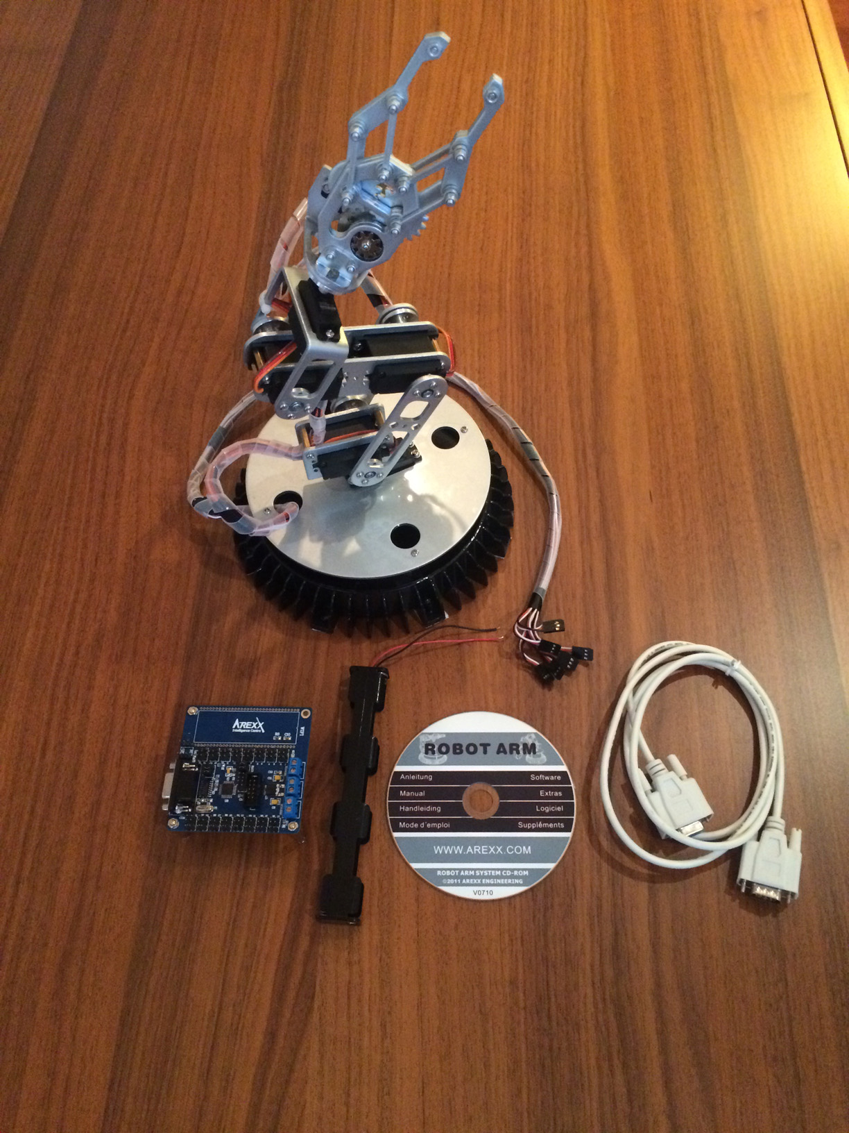
This is what came in the box.
Robot arm
32 Servo controller Board (Arexx)
6 battery holder
RS232 cable
CD-ROM ( Yep, a CD-ROM.)
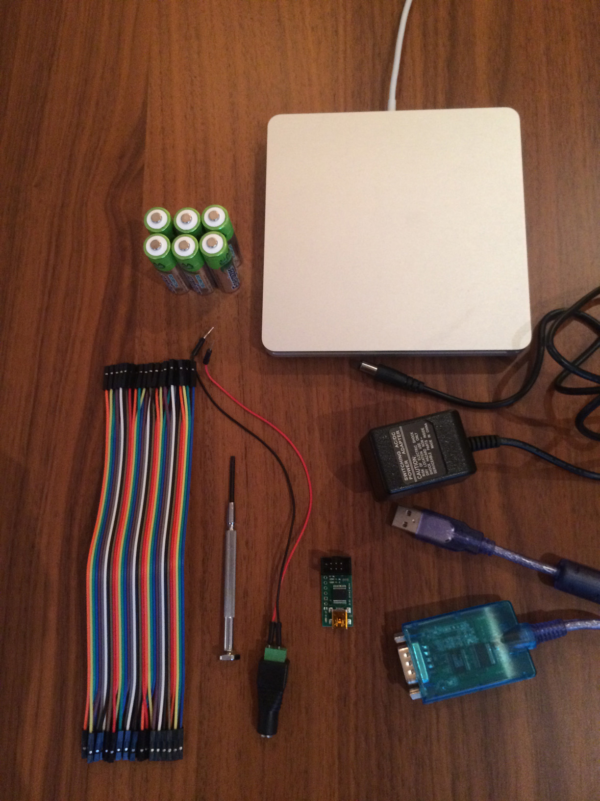
These are the things that did not come in the box.
6 AA batteries
5V 2A (2000mA) switching power supply - UL Listed
USB to RS323 converter cable
USB AVR Programmer (ISP) with STK500 support
Female DC Power adapter - 2.1mm jack to screw terminal block
Screw driver
Male/Male Jumper wires
Female/Female Jumper wires
CD-ROM reader ;)
Let's start from the top. The Arexx board is capable of controlling 32 servo motors (the arm has 6). That's pretty cool! However, when it arrives, it is not yet capable of controlling anything. You have to load a program onto the Atmega168 (MCU). To do that you need several things:
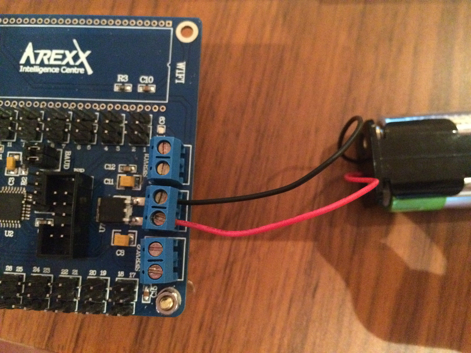
- 6 AA batteries
- A screw driver
- USB AVR Programmer (ISP) that supports STK500
- Female/Female Jumper wires
- A CD-ROM drive
There is a line in the english manual that says
"reserve the ISP downloaded, you can download the MCU controller program using the STK500 ISP cable".
Here are the steps to program the chip. (Just a note that I did this on Windows 8 in Bootcamp on my Macbook Pro.)
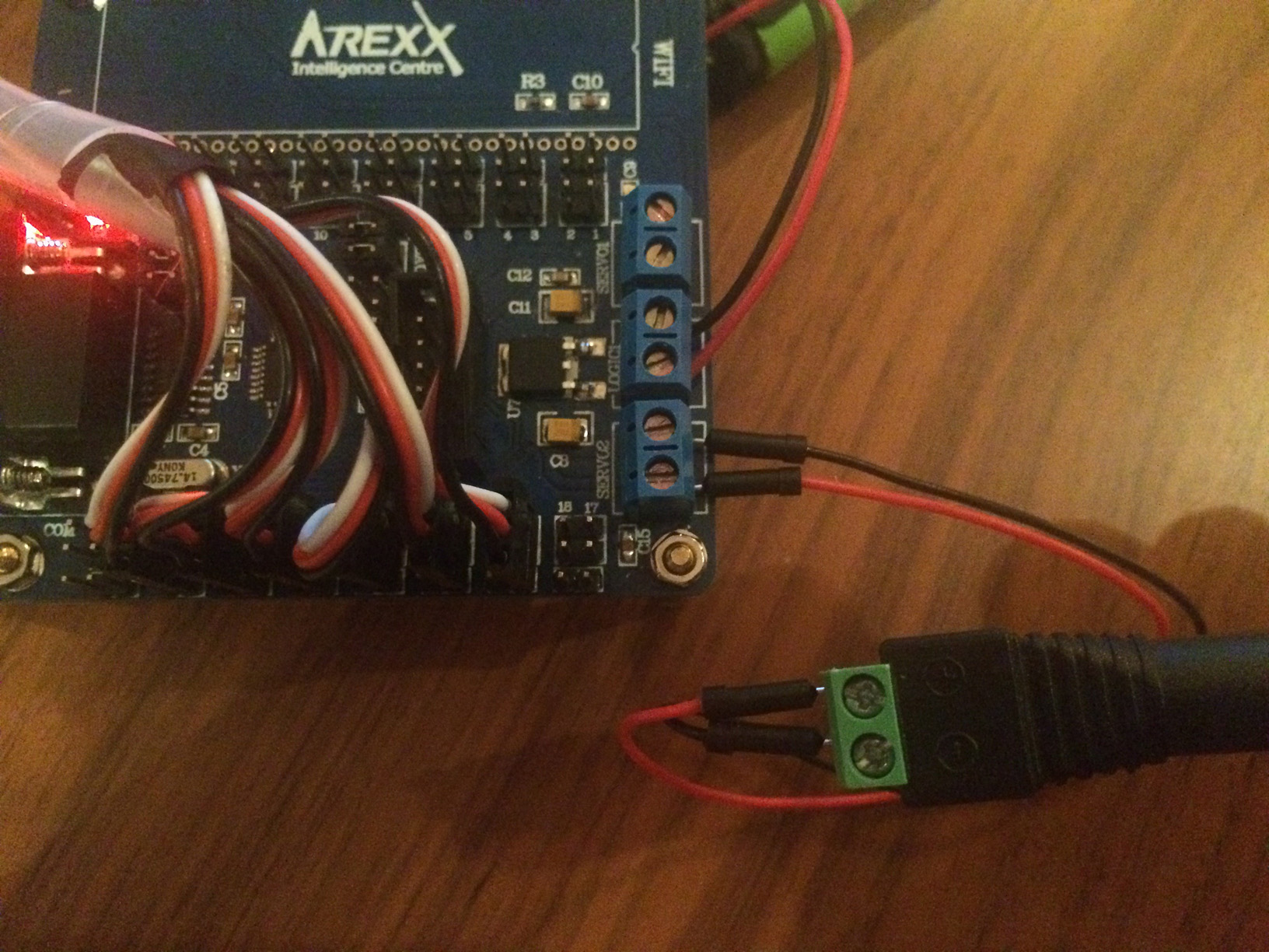
Power the board (MCU) using the batteries and battery holder provided. The red cable is power, the black is ground. Using the screw driver, secure the cables to the center screw terminal as shown.
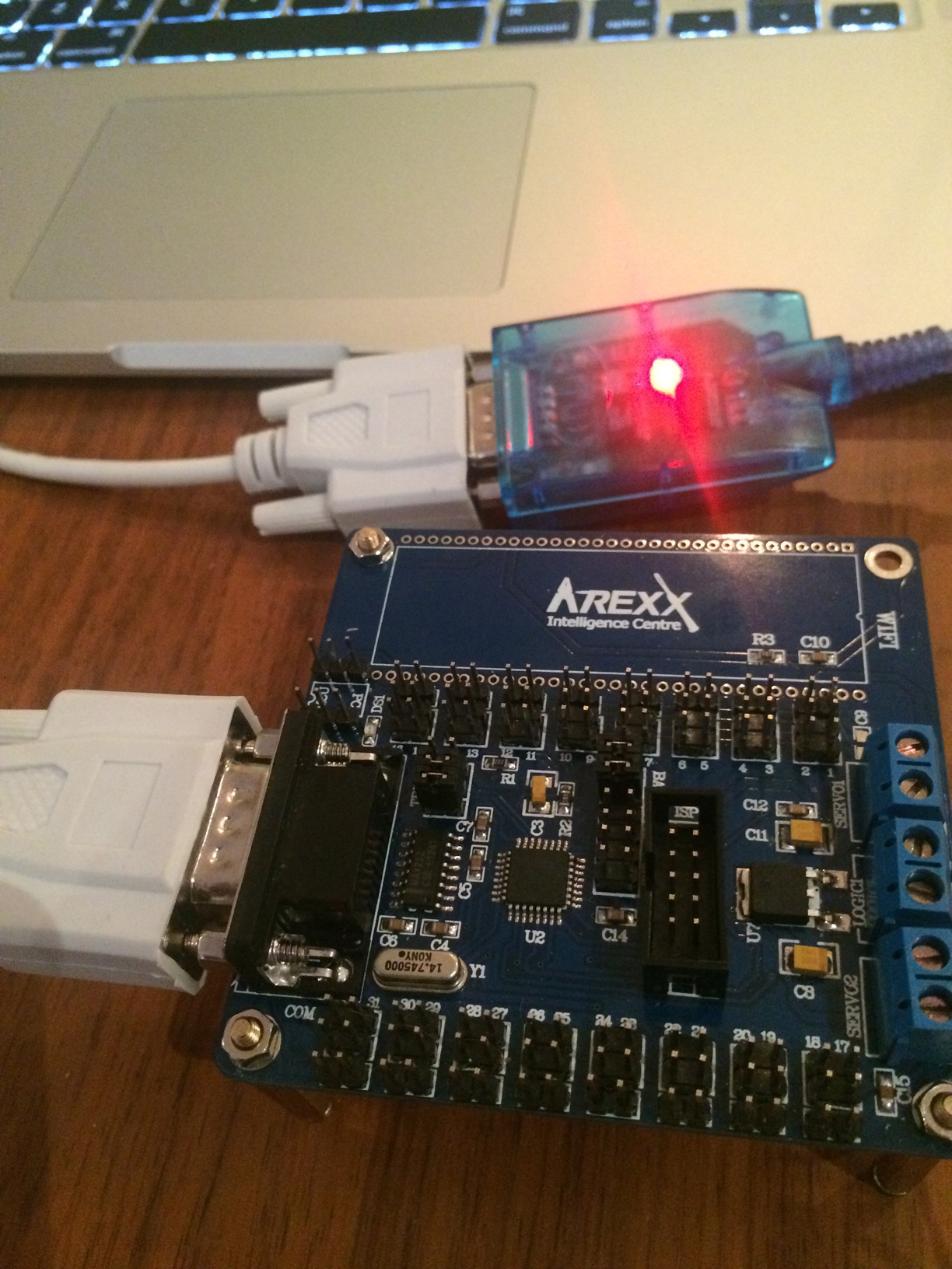
Connect your USB Programmer to the ISP port on the board. You may also need to install a driver for your programmer cable.
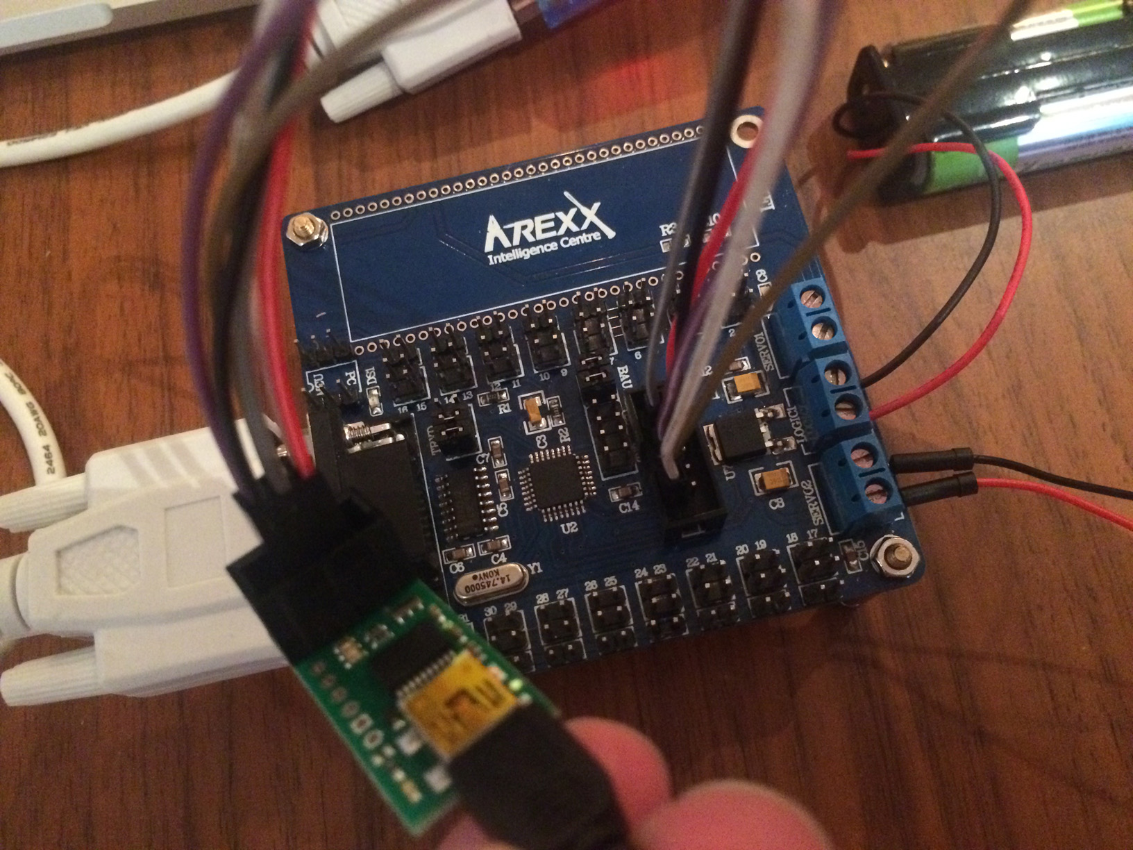 In my case, I had a 6-pin programmer. The ISP connection on the Arexx board has 10-pins. Here's how you can map those pins if needed and this is where the female/female jumper wires came in handy.
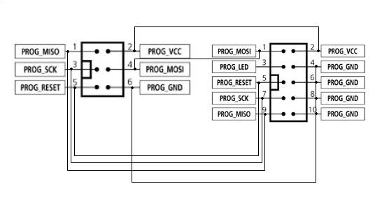
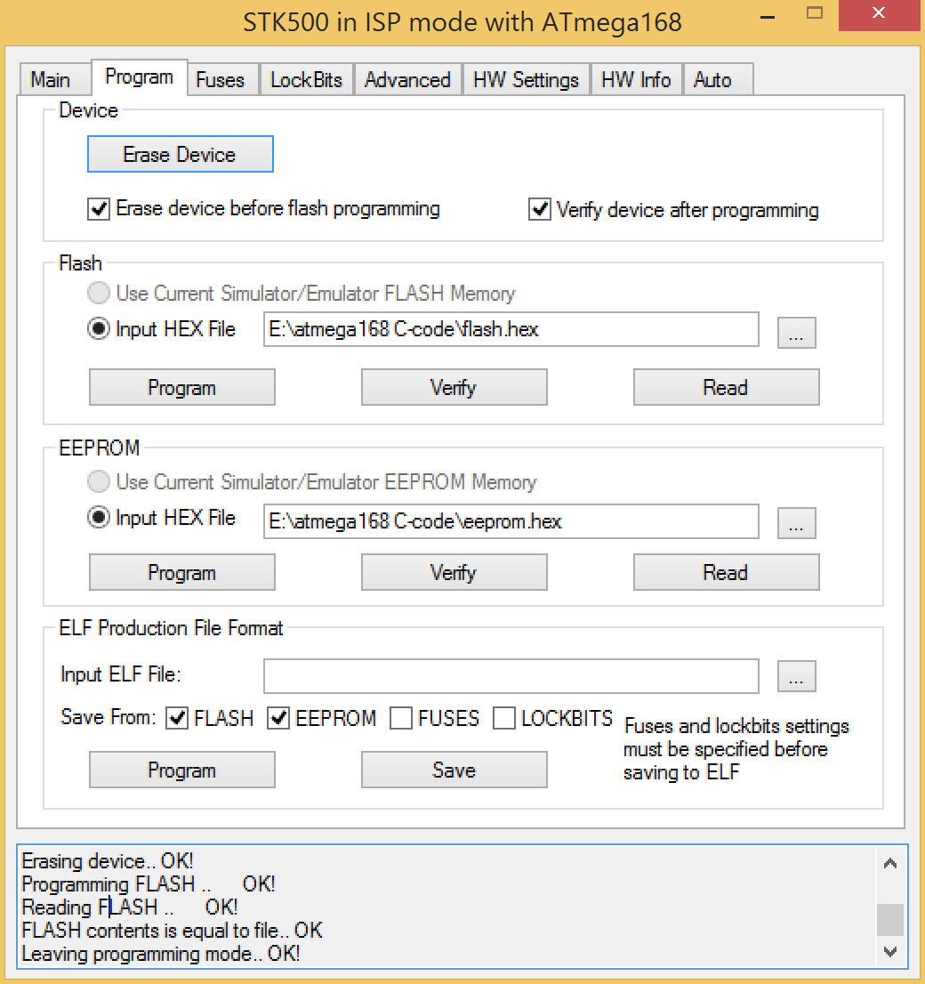
Install AVRStudio4 from the CD-ROM provided.
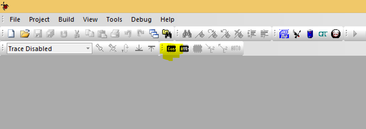
Open AVRStudio4 and select Tools > Program AVR (or click the highlighted button
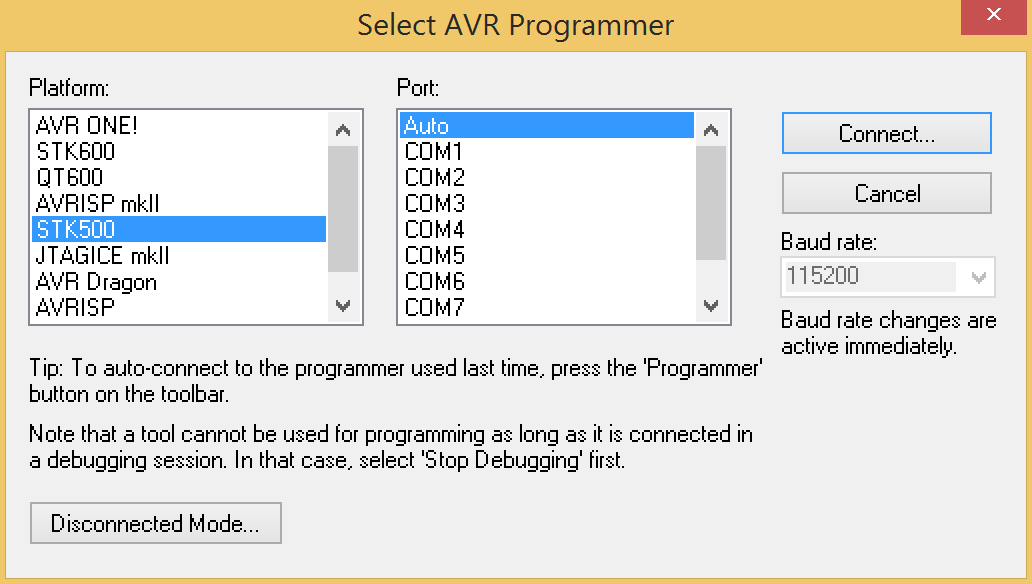
Choose STK500 and Auto and clickConnect.
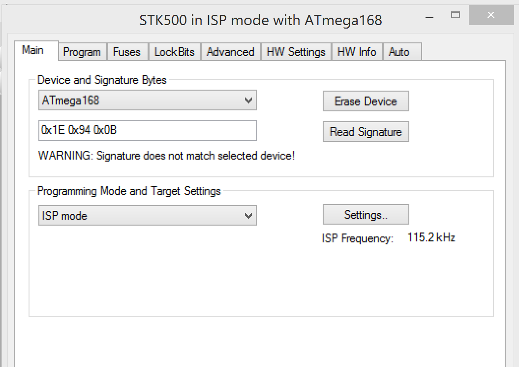
Select ATmega168 in the dropdown and if you are able to read the signature go to the Program tab.
 Select the hex from the CD-ROM
 /atmega168 C-code/flash.hex And hit program in the Flash section here
If that all goes successfully you are ready to make the arm move. You will these items:
- USB to RS232 cable
- 5V 2A (2000mA) switching power supply - UL Listed
- Female DC Power adapter - 2.1mm jack to screw terminal block
- Screw driver
- Male/Male Jumper wires
- A CD-ROM drive
Here are the steps to send serial data using a USB to RS232 adapter cable.
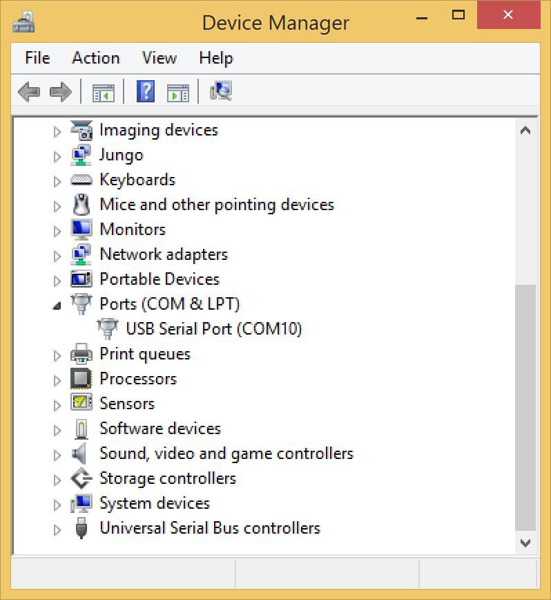
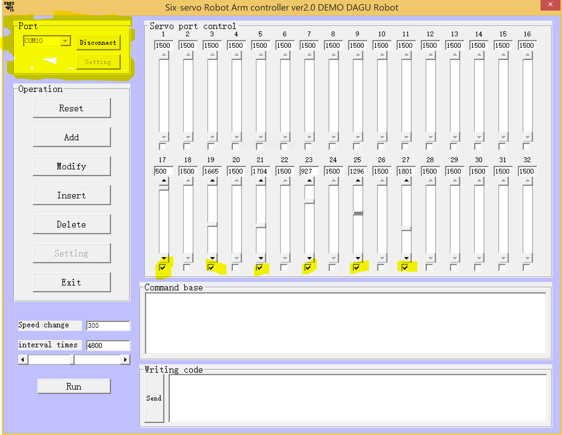
- First install the driver for your USB to RS232 cable. In my case I also needed to give it a COM port number in Device Manager, I chose COM10.
Here's the cable connected to the board.
 Once your driver is installed it should show up in Device Manager.
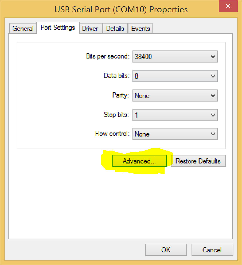
 You can set the COM port in the advanced tab.
 2. Next install the robot arm controller software from the CD. If you are not able read Chinese follow the
 install_step.pdf on the CD-ROM to navigate the dialog windows.
3. Connect the servo motor cables to your board. The black cables are ground and should face the bottom of the board if you use the bottom row.
4. Power the bottom row of servos with the 5V power supply, the DC power adapter, and two Male/Male jumper cables.
 4. Open the software just installed, it is called
 s32. Connect to the COM10 port you just created, and from here it should be pretty straight forward to manually control the arm. Just click the numbers you connected your servo cables to and you are good to go.
The next step is controlling the motors without the GUI by sending serial data directly to the atmega, but more on that in another post.